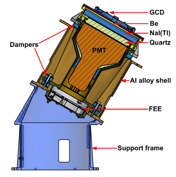
As the main detecting unit, each GRD contains an NaI(Tl) crystal box, photomultiplier, magnetic shielding, high-voltage distributor, front-end electronics, and mechanical structures. The NaI(Tl) crystal, which has a diameter of 160mm and thickness of 15mm, is the sensitive material that the incoming gamma photons will interact with to produce scintillation fluorescence with a decay time of ∼250ns and maximum emission wavelength of ∼415nm. The entrance window material of the crystal box is beryllium which was rolled to a thin thickness of 1.5mm to increase the transmittance of low-energy X-ray. The ESR reflection film is used to wrap the top and sides of the NaI(Tl) crystal, which is coupled with the quartz glass with a thickness of 15mm by silicone gel. The size of the quartz glass is matched to the PMT coupling end to improve the collection efficiency of scintillation fluorescence. The PMT R877-100 with 5-inch window, which is produced by the Hamamatsu Company, is selected to collect the scintillation fluorescence, and two magnetic shielding films are laid on the inner side of the GRD shell and the outer side of the PMT to reduce the influence of magnetic fields on the detector. The GRD electronics, including the charge-sensitive preamplifier, differential amplifier drive circuit and high-voltage power supply circuit, are responsible for amplitude signal conversion, signal amplification, and power supply for the PMT. A large dynamic range of GRD is achieved by the design of the high-gain and low-gain channels in the preamplifier. Each GCD consists of a plastic scintillator BC-440M with an embedded 241Am source inside, one silicon photomultiplier (SiPM) and readout electronics. By selecting the coincident signal of the alpha-particle event in GCD and the gamma-ray event in GRD, GRM can distinguish the gamma-ray events of 241Am from other sources. The coincident gamma-ray spectrum can be used to monitor the performance changes of GRD on orbit. The figure shows the GRD module structure with GCD installed on its top surface.
The schematic diagram of GRD is as Fig 2:

Fig 2: Schematic diagram of GRD

